

How Can We Help?
Configure the 2N Helios IP Vario video intercom
The 2N Helios IP Vario device is an IP video door entry unit which, configured in connection with a VOIspeed switchboard, allows the use of an audio / video door entry station with the possibility of door or gate opener (see technical specifications) and to reproduce images on videophones connected to the VOIspeed switchboard or on the PCs of your network (directly from the WEB page).
Self-provisioning
The device can be configured with the PBX self-provisioning procedure, so you can skip reading the entire manual and go directly to the PBX: the self-provisioning procedure will show at the end a link to a short manual on how to continue the configuration.
Connecting the device to the LAN
To connect the device to the LAN of the structure in which it is to be inserted, it is necessary to use the terminal block supplied with the video door phone and connect an RJ45 cable to it following the instructions in the following document.
Once the device is connected to the LAN, it is possible to access its WEB configuration by typing the IP address of the device in the address bar of any browser. The device is configured to dynamically acquire an IP address from a DHCP server. In this case, to know the IP address, it is possible to operate in 3 ways:
- use a network scanner or analyze the DHCP server information, or
- use the 2N proprietary scanner which only returns the list of 2N systems, which can be downloaded at this address
- after turning on the intercom and hearing the 3-tone sequence that identifies the activation of the LAN interface, quickly press the call button 5 times. If the IP is acquired, a recorded voice will dictate it, if the voice reads “0.0.0.0”, the IP is not yet acquired and you will have to proceed with one of the previous methods.
Home page of the device
| Upon entering the device configuration, you arrive at the home page from which you can get to each configuration section. Each box corresponds to a specific configuration area of the device. | 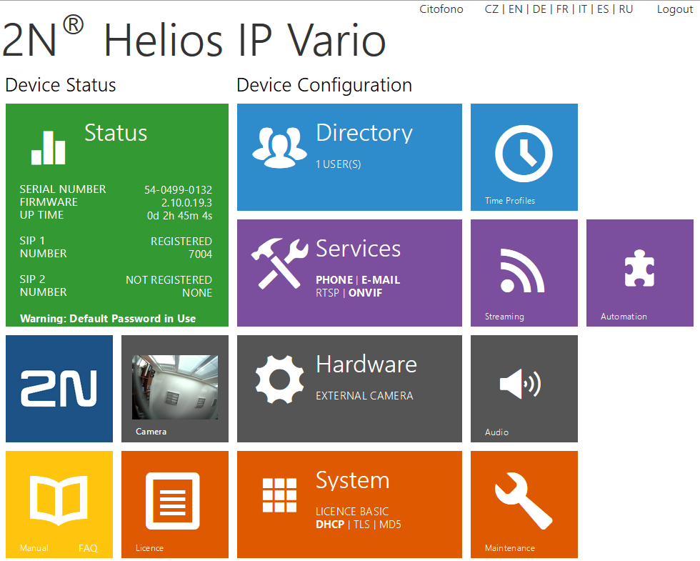 |
Configuration – SIP User
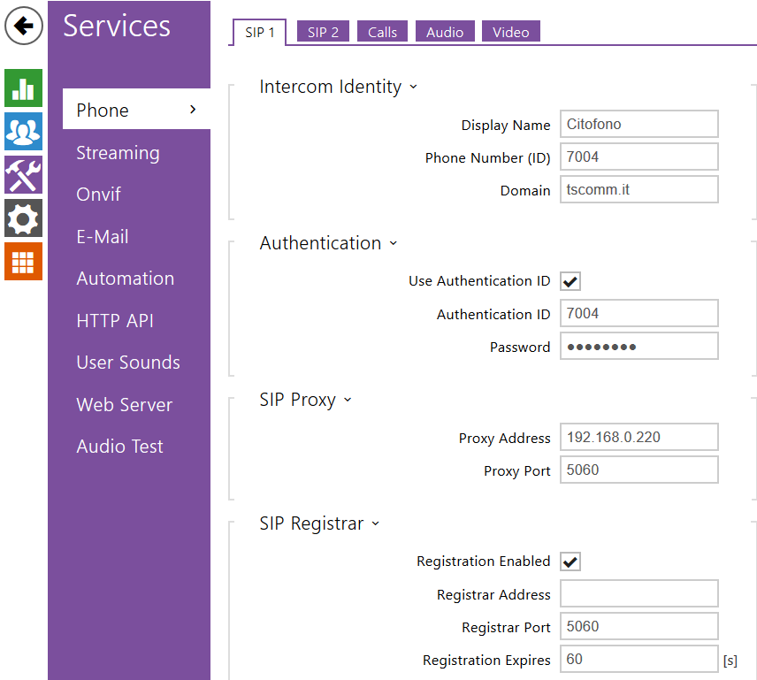
Click on the services section ![]() and Phone menu. It is possible to set the parameters for the operation of the device with the VOIspeed PBX. In particular, the items must be configured:
and Phone menu. It is possible to set the parameters for the operation of the device with the VOIspeed PBX. In particular, the items must be configured:
| Intercom Identity
Display Name: user convenience name Authentication Use authentication ID: set to “Yes” SIP Proxy Proxy address: the IP address of the VOIspeed server SIP registrar Registration Enabled: set to “Yes” |
 |
Configuration – Basic Settings–> Phone Book
In the Basic Settings -> Phone Book section it is possible to set the numbers that will be called by the interphone when one of its call keys is pressed.
N.B. For the use of the model described in this manual we will limit ourselves to the description of position 1.
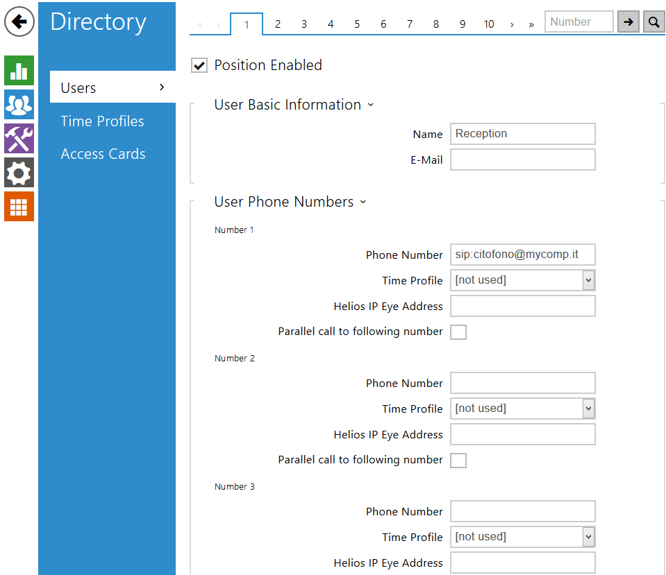
In the Phone book interface it is necessary to configure:
General settings
Position enabled: Yes. In this way the position will be declared active and pressing the corresponding key on the interphone will make a call to the switchboard according to the subsequent settings.
Phone numbers
The telephone numbers that the intercom will try to contact are configured here. By default, the intercom will call the first number and, if unreachable, will try with the second and then with the third unless different settings are highlighted in the detail of the following individual items
Number 1: It is the first number to be contacted directly by the intercom, which will automatically make a call to this number when the activated key is pressed. Here a VOIspeed extension or an entire group can be specified (in this case the number specified in this field must be managed via a routing rule in VOIspeed that forwards the call for this number to the group in question)
Group call: Allows you to decide whether the call should be addressed only to the first number specified or also to the next number simultaneously. If you have already created an intercom response group within the VOIspeed Server, you do not need to activate this option
User switch codes: Allows you to assign a selection code for each switch that can be activated. In the simple case (a door to be controlled by the single intercom installed) it is sufficient to assign a code to the first switch. To communicate the code from the phone it will then be necessary to write the code followed by the asterisk character: for example 11 * (default)
Configuration – Basic Settings–> Switch 1
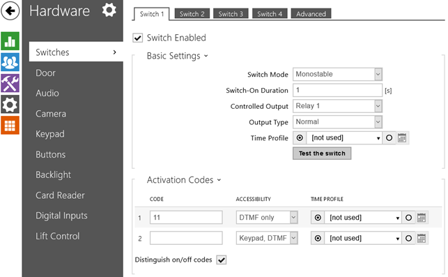
This section shows the activation codes of the switches and the characteristics of the relative switch for controlling a door opener.
N. B.For the use of the model described in this manual we will limit ourselves to the description of switch 1.
Switch settings
Switch enabled: Yes.This will enable the switch for opening the door. Otherwise the intercom will not accept any code
Switch mode: Monostable. In this way, pressing the code will activate the switch which will deactivate automatically after an amount of time in seconds equal to the parameter set below
Switch-on duration: Time in seconds of activation duration (in the excited state) of the switch. Indicates how long the activation voltage will be applied to the switch. We can take 2 seconds as a reference for normal door openers, but in different cases consult with your electrician.
Controlled Output: Relay 1. Indicates the relay to be energized (relay1 is the basic integrated relay, in case of adding other relays, it will appear in this list; select the desired one)
Output type: normal.
Test the switch: simulates pressing the key just configured without physically going to the external unit
Activation codes
Here you can set the code that activates the door opener relay. Configure the code in field 1, setting:
Code: numeric code which, when typed by the telephone that answers the call from the intercom, activates the switch.
Nota: The opening procedure involves typing the “asterisk” end-of-entry character immediately after entering the opening code. For example: if the code chosen in the Code box was 11, you must enter 11 from the phone *
Accessibilty: indicate the method of transmission and acceptance of the tones. If an external keyboard is not installed, set DTMF only or Keyboard, DTMF
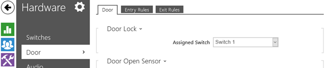 Door Lock
Assigned Switch: indicates the switch associated with the door opener. Set Switch1
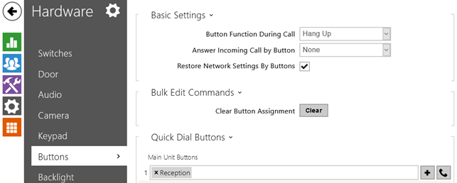
Quick Dial Button: logically associates the hardware switch with the user configured in the Directory. Without this there would be no association between pressing the button and the SIP call. Press the “+” button and choose the user already configured in position 1 of the directory.
Visualization of the video stream on phones with graphic displays
If the user responsible for opening the door has a graphic IP phone, it is possible to view the video stream captured by the video door entry unit directly on his display, if the phone supports the H263, H263 + and H264 video codecs.
Warning: in the case of Polycom phones, a special integration must be activated in the video door entry unit. In the Advanced Settings menu, Video Codecs – Advanced RTP settings, enable the Polycom compatibility mode (ON) option.